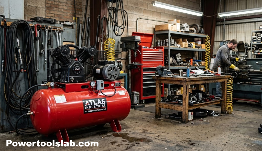
How Air Compressors Work: The Complete Guide to Compressed Air Systems
From the motor that spins the pump to the trigger that fires your nail gun — here’s exactly what happens inside an air compressor, explained without the jargon.
The Basic Idea Behind Compressed Air
An air compressor looks complicated from the outside — a metal tank, a hunk of a motor, a coil of hose, a gauge or two — but the principle running underneath all of it is almost embarrassingly simple. Air, like any gas, can be squeezed into a smaller space than it naturally wants to occupy. When you force a given amount of air into a container smaller than its natural volume, the molecules get pushed closer together, they collide more often, and the pressure inside that container rises. That’s it. That’s the whole trick. Every air compressor ever built, from a $40 tire inflator to a 200-horsepower industrial rotary screw unit, is just a machine designed to do that squeezing in a controlled, repeatable, and safe way.
What makes this useful is that compressed air stores energy. Squeeze air into a tank and you’ve essentially loaded a spring. Open a valve and that stored energy rushes back out, and if you aim that rush of expanding air through a nozzle, a piston, or a turbine, you can use it to do real mechanical work — drive a nail, spin a grinder, inflate a tire, blast dust off a workbench, or actuate an industrial cylinder. Compressed air is, in a very real sense, a portable and reusable form of stored energy, and understanding how a compressor builds and manages that stored energy is the key to understanding the whole machine.
Before we go further, it helps to fix a mental picture in place. Picture a bicycle pump. You push the handle down, a piston inside a cylinder moves, air gets squeezed ahead of the piston, and once the pressure ahead of the piston is higher than the pressure inside your tire, a one-way valve opens and lets that pressurized air flow into the tire. An air compressor is, at its heart, a bicycle pump that has been automated: a motor pushes the piston instead of your arm, the compressed air goes into a steel tank instead of a tire, and a pressure switch decides when the motor should keep pumping and when it should rest.
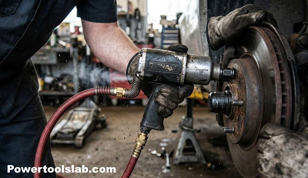
Once you have that bicycle-pump mental model locked in, the rest of this guide is just filling in detail: what the piston and cylinder actually look like inside a real compressor, how the motor is sized and wired to drive that piston, how the tank is built to hold pressure safely, how the machine knows when to turn itself on and off, and how all of that pressurized air gets metered back out at a pressure your tools can actually use. We’ll also walk through the different compressor architectures on the market, explain the difference between the two numbers every buyer obsesses over — PSI and CFM — and cover the maintenance habits that keep a compressor running for a decade instead of two years.
Why Compressed Air Became the Shop Standard
It’s worth pausing on why so much of the tool world runs on compressed air in the first place, rather than, say, battery power or a direct mechanical linkage. Compressed air has a handful of properties that make it uniquely suited to shop and industrial work. First, a single central compressor can supply an entire shop full of tools through a network of hoses or fixed piping, meaning the expensive, heavy, and maintenance-intensive part of the system — the motor and pump — only has to exist once, not once per tool. Second, pneumatic tools built to run on compressed air tend to be lighter and more compact than their electric or hydraulic equivalents, because they don’t need to carry their own motor or battery; a pneumatic impact wrench, for example, is often noticeably lighter than a comparable cordless model, which matters over a long shift.
Third, air tools are inherently more forgiving of stalling and overload than electric motors. If you jam an air-powered drill or impact wrench, the tool simply stalls without damage and resumes the moment the obstruction clears, whereas stalling an electric motor under load can burn out windings in seconds. Fourth, compressed air systems are relatively immune to the electrical hazards that come with running high-powered electric tools in wet, dusty, or otherwise hazardous environments — a pneumatic tool carries no risk of electrical shock even if used somewhere damp, which is one reason compressed air remains standard in automotive shops, where fluids and moisture are a constant presence.
None of this means compressed air is free — you’re paying for it in electricity to run the compressor motor, and pneumatic systems are inherently less efficient at the point of use than a direct electric or battery-driven tool, because energy is lost converting electrical power to mechanical compression and then back to mechanical work at the tool. But for shop environments where multiple tools, heavy-duty cycling, and durability under abuse matter more than raw energy efficiency, the tradeoff has made sense for well over a century, and it’s why compressed air infrastructure remains a fixture in garages, manufacturing floors, and construction sites worldwide.
A Brief History of the Air Compressor
The core idea behind compressed air is ancient — bellows used to feed forges with a stream of air date back thousands of years, and they’re arguably the earliest ancestor of the modern air compressor, since a bellows is really just a manually operated pump that pushes air where it’s needed. The leap toward something recognizable as a modern compressor came during the industrial era, when engineers began building mechanical pumps driven by steam engines to supply compressed air for mining operations, where compressed air could power drills and other equipment deep underground without the danger of running electrical cable or combustion engines in confined, poorly ventilated spaces.
Compressed air mining drills in the 1800s proved the concept at industrial scale, and from there compressed air systems spread into manufacturing, where they powered everything from pneumatic hammers to early assembly-line tools. The 20th century saw the electric motor replace steam as the standard drive source, tank and pump designs become dramatically more compact and efficient, and safety standards formalize around pressure vessel construction after a series of early tank failures made clear that a compressed air tank needed the same engineering rigor as a boiler. By the mid-1900s, the same basic architecture used in today’s home-shop compressors — electric motor, piston pump, steel tank, automatic pressure switch — was already well established, and most of the progress since then has been about refining efficiency, reducing noise, and shrinking the package rather than reinventing the underlying mechanism.
Anatomy of an Air Compressor
Strip away the paint and the shroud, and nearly every reciprocating air compressor — which is to say, the piston-driven type found in the overwhelming majority of home garages, hobby shops, and small job sites — is built from the same core set of parts. Getting familiar with each one makes every other section of this guide click into place.
The Motor
The motor is the machine’s muscle. In most consumer and light-commercial compressors it’s an electric induction motor, though gas-powered engines are common on portable job-site units that need to run far from an outlet. The motor’s only job is to spin a crankshaft, which in turn drives the piston (or pistons) back and forth inside the pump.
The Pump
The pump is the compression mechanism itself — the cylinder, piston, connecting rod, valves, and crankshaft that physically squeeze the air. This is the component most people mean when they casually say “compressor,” even though technically the whole assembly, motor and tank included, is the compressor.
The Tank (Receiver)
The tank, sometimes called the air receiver, is a sealed steel or aluminum vessel that stores the compressed air the pump produces. It acts as a buffer, letting you draw a burst of air faster than the pump alone could generate it, which is why a compressor can power a nail gun’s rapid-fire trigger pulls even though the pump itself cycles far more slowly.
The Pressure Switch
This is the automatic on/off brain of the unit. It senses tank pressure and starts the motor when pressure falls below a set point, then stops it once pressure climbs back up to a second, higher set point.
The Regulator and Gauges
The regulator lets you dial down the pressure delivered to your hose and tool, independent of what’s stored in the tank. Two gauges typically flank it: one showing tank pressure, one showing regulated output pressure.
The Safety Relief Valve
A small spring-loaded valve, usually mounted directly on the tank, that vents air automatically if pressure ever climbs dangerously high — a mechanical failsafe that exists independently of the pressure switch’s electronics.
The Check Valve, Drain Valve, and Filters
A check valve keeps compressed air from flowing backward into the pump once it’s in the tank. A drain valve at the tank’s lowest point lets you release condensed moisture. Intake filters keep dust and debris out of the pump’s intake stroke.
How These Parts Are Arranged on Common Compressor Styles
The exact physical layout of these components varies by compressor style even though the underlying function stays identical. On a pancake compressor, the tank is a flat, wide disc that doubles as the base the pump sits directly on top of, prioritizing a low center of gravity and stable footing over portability by hand. On a hot-dog or twin-stack style unit, the tank is a horizontal cylinder, or two smaller cylinders, mounted beneath or beside the pump, favoring a compact footprint that’s easy to tuck under a workbench. Wheelbarrow and cart-style units mount a larger horizontal tank on a two-wheeled frame with a handle, trading compactness for the ability to roll a bigger tank around a job site. Stationary shop compressors typically mount a large vertical tank on the floor with the belt-driven pump assembly on top, prioritizing tank capacity and pump longevity over any need to move the unit around, since it usually lives permanently in one corner of the shop feeding a fixed air line.
If you’re shopping rather than just researching, our guide on how to choose an air compressor walks through matching these components to your actual tools and workload before you buy.
The Motor and Pump: Where Compression Actually Happens
The motor-and-pump assembly is where the real transformation happens — electrical or fuel energy going in, pressurized air coming out — so it’s worth slowing down here.
How the Piston Compresses Air
Inside the pump’s cylinder, a piston moves up and down (or back and forth, depending on orientation), driven by a connecting rod attached to a rotating crankshaft, exactly like the mechanism inside a car engine, just running in reverse purpose. On the piston’s downstroke, or intake stroke, a spring-loaded intake valve opens and atmospheric air is pulled into the cylinder as the piston creates a low-pressure area. On the upstroke, or compression stroke, that intake valve slams shut, sealing the air inside the shrinking cylinder volume. As the piston continues upward, the trapped air has nowhere to go, so its pressure rises rapidly. Once the pressure inside the cylinder exceeds the pressure already sitting in the tank, a second one-way discharge valve is forced open, and the compressed air is pushed out of the cylinder, through the check valve, and into the tank.
This cycle — intake, compression, discharge — repeats hundreds of times per minute. A typical single-cylinder pump running at standard household voltage might complete somewhere in the neighborhood of 800 to 1,000 full strokes per minute, which is why compressors sound like a rapid mechanical hammering rather than a smooth hum.
It’s worth noting that this rapid cycling also generates a surprising amount of heat, and heat is really the pump’s biggest long-term enemy. Compressing a gas inherently raises its temperature — this is the same basic thermodynamic principle that makes a bicycle pump’s barrel warm to the touch after a few strokes. On a small compressor doing occasional light work, that heat dissipates harmlessly into the surrounding air between cycles. On a compressor pushed well past its rated duty cycle, heat can build up faster than it escapes, softening lubricants and accelerating wear on rings and bearings. This is exactly why pump housings are almost always finned — those ridges cast into the cylinder head aren’t decorative, they maximize surface area so heat can radiate away between strokes.
Cooling is also why pump placement matters more than most buyers realize. A compressor tucked into a tight, unventilated cabinet, or one running in a hot, unshaded space, will run hotter than the same unit sitting in open shop air, and that extra heat quietly shortens component life even if nothing ever fails outright. Giving a compressor a few inches of clearance on all sides, and keeping the intake filter free of dust that would otherwise restrict airflow across the finned housing, are two of the simplest habits that keep pump temperatures in a healthy range over years of use.
Single-Cylinder vs Twin-Cylinder Pumps
Small pancake and hot-dog style compressors typically use a single cylinder. Larger shop and industrial units often use two cylinders working off the same crankshaft, either compressing air in parallel for higher volume (more CFM) or in series for higher pressure — the second cylinder taking the already-compressed output of the first and squeezing it further.
Single-Stage vs Two-Stage Compression
In a single-stage compressor, the piston compresses air from atmospheric pressure all the way to final tank pressure in one continuous stroke. This is efficient, mechanically simple, and perfectly adequate for the pressure ranges most home and small-shop tools need, generally up to around 135 to 150 PSI.
A two-stage compressor splits that job across two cylinders of different sizes. The larger, low-pressure cylinder compresses air partway, then routes it through an intercooler — essentially a small radiator — to a smaller, high-pressure cylinder that finishes the job. Cooling the air between stages matters because compression generates heat, and hot air is harder to compress efficiently and holds more moisture. By cooling between stages, a two-stage design can reach much higher pressures, often 175 PSI and beyond, with less strain on the pump and better long-term efficiency, which is why two-stage units dominate industrial and heavy continuous-duty settings.
| Feature | Single-Stage | Two-Stage |
|---|---|---|
| Typical max pressure | Up to ~150 PSI | 175+ PSI |
| Best for | Home, hobby, light commercial | Industrial, continuous-duty shops |
| Efficiency at high pressure | Lower | Higher |
| Upfront cost | Lower | Higher |
| Mechanical complexity | Simple | More complex, intercooler included |

Shopping for a reliable shop compressor?
See our current top-rated pick for home and light commercial use — sized to keep up with nail guns, impact wrenches, and sanders without constant motor cycling.
Check Current Price on AmazonThe Tank: Storing Pressurized Air Safely
The tank, or air receiver, is more than a passive holding container — it’s an engineered pressure vessel, and its design directly affects how the compressor performs. A larger tank stores more compressed air, which means it can supply a burst-demand tool, like a framing nailer firing rapidly, for longer before the pump has to kick back in. It also means the motor cycles on and off less frequently, which reduces wear and extends motor life.
Vertical vs Horizontal Tanks
Vertical tanks stand upright and have a smaller footprint, making them popular for shop corners where floor space is tight. Horizontal tanks lay on their side, often mounted on a wheeled frame or beneath a pancake-style pump, and tend to offer a lower center of gravity that’s useful for job-site portability.
Tank Material
Most tanks are welded steel, which is strong, inexpensive, and easily repairable, but is also vulnerable to internal rust if moisture is left sitting inside it. Some portable and pancake-style compressors use aluminum tanks instead, trading a bit of strength for meaningfully lower weight and total corrosion immunity, which is why aluminum-tank units are popular with roofers and other trades who carry a compressor up and down ladders all day.
Why Tank Size Matters More Than People Expect
Two compressors can share an identical pump and motor and still perform completely differently in real use if their tanks are different sizes. A small 6-gallon tank paired with a tool that needs a sustained high CFM draw — a die grinder, for example — will drain almost instantly, forcing the motor to run nearly continuously. A 20 or 30-gallon tank paired with the same tool gives you a much longer window of usable air before the pump has to catch up, and it also smooths out pressure fluctuations, which matters for tools like spray guns where inconsistent pressure shows up as an inconsistent finish.
Pre-Charged Air and the “Battery” Analogy
A useful way to think about tank size is to treat it like a battery pack rather than a plumbing fixture. Just as a bigger battery gives a cordless tool more runtime between charges, a bigger tank gives a pneumatic tool more runtime between motor cycles. The pump is analogous to the charger — it can only replenish stored energy at a fixed rate, set by its CFM output — while the tank is the reservoir that lets you draw energy faster than the charger alone could supply, at least for short bursts. This is exactly why a small compressor can still fire a nail gun rapidly for a few seconds even though its pump alone couldn’t keep up with that firing rate indefinitely: the tank is loaning out pressure it stored up during the previous rest period, and the pump has to work to pay that loan back once you stop.
How Tank Pressure Rating Interacts With Altitude and Temperature
Two secondary factors quietly affect how a tank performs day to day: ambient temperature and elevation. Cold air is denser than warm air, so on a cold morning a compressor can actually pack slightly more air mass into the same tank volume at the same PSI reading, while on a hot day the opposite is true. At high elevation, atmospheric pressure itself is lower, meaning the pump’s intake stroke starts from a lower baseline pressure, which can modestly reduce both maximum output pressure and CFM delivery compared to sea level. Neither effect is usually large enough to worry about for typical shop work, but it explains why the same compressor can feel slightly different to use in Denver in January versus Miami in August.
Not sure what tank size and CFM output your projects actually require? Our breakdown of what size air compressor do I need matches tank capacity to real tool workloads.
The Pressure Switch and Duty Cycle
The pressure switch is the small, unglamorous component that does most of the thinking in an air compressor. It’s essentially a diaphragm connected to the tank’s internal pressure, wired to a set of electrical contacts. As tank pressure changes, the diaphragm flexes, and at two specific pressure points it physically opens or closes those contacts.
Cut-In and Cut-Out Pressure
Manufacturers set two thresholds: the cut-in pressure, the low point at which the switch closes the circuit and starts the motor, and the cut-out pressure, the high point at which the switch opens the circuit and stops the motor. A common consumer compressor might cut in around 90 PSI and cut out around 125 PSI, giving a 35 PSI working band. As soon as you draw air with a tool, tank pressure falls; once it drops to the cut-in point, the motor fires back up automatically and refills the tank until cut-out is reached again, at which point the motor shuts off and waits.
This automatic cycling is also why an air compressor can sit plugged in and ready for hours or days without running at all, and it’s a detail that surprises some first-time owners. As long as tank pressure stays above the cut-in threshold — which it will, indefinitely, in a leak-free system — the pressure switch has no reason to close the circuit, so the motor simply stays off. The moment you open a tool’s trigger and pressure begins to fall, the switch reacts within a second or two. This responsiveness is also why compressors are considered “ready” the instant they’re plugged in and the tank holds pressure from a previous session, rather than needing to be powered on and warmed up like some other shop equipment.
Duty Cycle
Duty cycle describes how much of the time a compressor’s motor is designed to actually run versus rest, expressed as a percentage over a set time window, commonly measured over 10 or 15 minutes. A compressor rated for a 50% duty cycle is engineered to run roughly half the time and rest the other half; pushing it to run continuously beyond its rated duty cycle is one of the most common causes of premature motor burnout. This is precisely why tank size matters so much — a bigger tank buys the motor more rest time between cycles for the same tool usage.
Adjusting the Pressure Switch Yourself
Most pressure switches allow some adjustment of both the cut-in/cut-out points and the differential — the gap between them — via small nuts or screws inside the switch housing, though this should only be attempted with the unit fully unplugged and depressurized, and never adjusted beyond the tank’s rated maximum working pressure. Narrowing the differential makes the motor cycle more frequently for shorter bursts, which some users prefer for more consistent pressure delivery, while widening it means longer, less frequent run cycles with a bigger pressure swing in between. Because this involves working inside a live electrical enclosure, many owners reasonably choose to leave factory settings alone unless there’s a specific documented reason to change them, or have a qualified technician make the adjustment.
The Regulator: Controlling Output Pressure
Tank pressure and delivered pressure are two different numbers, and the regulator is the component that separates them. Without a regulator, whatever pressure happens to be sitting in the tank at that moment would go straight down the hose to your tool, which is a problem, because tank pressure constantly swings between the cut-in and cut-out points, and many tools are only rated for a narrower, lower working pressure, commonly around 90 PSI.
The regulator is a spring-and-diaphragm valve that you adjust with a knob or dial. Turning it restricts or opens the passage between the tank and the outlet port, letting you dial in a steady, chosen output pressure regardless of whether the tank itself is sitting at 100 PSI or 140 PSI at that instant. This is what protects a delicate spray gun or a finish nailer from being blasted with more pressure than it’s built to handle, and it’s also how you fine-tune a tool’s performance — dialing down pressure slightly for lighter-gauge fasteners, for instance, or increasing it for a stubborn impact application.
Reading the Two Gauges
Most compressors display two separate gauges side by side: one reads tank pressure directly and will swing between cut-in and cut-out as the motor cycles, while the second reads regulated output pressure and should stay rock steady at whatever you’ve dialed in on the regulator knob, assuming tank pressure stays above your set point.
PSI vs CFM: What They Actually Mean
These two specifications cause more buyer confusion than everything else on a compressor’s spec sheet combined, so it’s worth a dedicated, no-nonsense explanation.
PSI — Pounds per Square Inch
PSI is a measure of force, specifically how hard the compressed air is pushing per square inch of surface area. Higher PSI means more force behind the air, which matters for tasks like driving a fastener deep into hardwood or breaking loose a rusted bolt with an impact wrench.
CFM — Cubic Feet per Minute
CFM measures volume flow — how much air, by volume, the compressor can deliver continuously in one minute at a given pressure. This matters enormously for any tool that consumes air continuously rather than in short bursts. A framing nailer that fires occasionally barely dents your CFM supply, but a die grinder or a sandblaster that consumes air the entire time the trigger is held will quickly outpace a compressor with a low CFM rating, causing pressure to sag mid-task even if the tank started full.
Why You Need Both, Not Just One
Think of PSI as how hard the water sprays from a hose and CFM as how wide the hose actually is. A tool needs enough PSI to have force, and it needs enough sustained CFM to keep that force available without the supply choking off. A compressor with plenty of PSI but too little CFM will still leave a continuous-draw tool starved of air and underperforming.
The 1.5x Rule for Buying Decisions
A widely used shortcut when matching a compressor to a tool is to look at the tool’s rated CFM at 90 PSI and multiply it by roughly 1.5. This buffer exists because manufacturer CFM ratings are typically measured under ideal, sustained conditions, while real-world compressor output is affected by hose length, fitting restrictions, ambient temperature, and normal wear over time. Buying a compressor whose CFM output only just matches a tool’s minimum rating on paper often means the tool feels noticeably underpowered once it’s actually connected through 25 feet of coiled hose in a warm garage — building in that buffer up front avoids a frustrating and entirely avoidable disappointment after purchase.
SCFM vs CFM: Reading Spec Sheets Correctly
Not all CFM numbers on a spec sheet are directly comparable, which is a common source of buyer confusion. SCFM, or Standard Cubic Feet per Minute, is measured under standardized reference conditions for temperature, pressure, and humidity, making it the more trustworthy figure for apples-to-apples comparison between different compressor models. Plain CFM, sometimes called displacement CFM or piston displacement, is calculated theoretically from the pump’s physical dimensions and stroke rate, and it’s almost always a noticeably higher, more flattering number than the SCFM the compressor will actually deliver in real use. When two similarly priced compressors seem to have wildly different CFM ratings, checking whether both figures are SCFM often explains the gap — and it’s the SCFM figure that should drive your buying decision.
How Hose Length and Diameter Affect Real-World Performance
Even a perfectly matched compressor and tool combination can underperform if the hose connecting them is too long, too narrow, or has too many quick-connect fittings creating restriction points. Air flowing through a hose experiences friction against the hose walls, and that friction increases with length and decreases with diameter, meaning a long, narrow hose can meaningfully drop the pressure actually reaching your tool compared to what’s showing on the tank gauge. For most home shop tools, a 3/8-inch inner diameter hose is a reasonable minimum, stepping up to 1/2-inch for higher-CFM tools like sandblasters or when running a hose more than 50 feet, and keeping the number of coupler connections to a minimum, since every quick-connect fitting introduces its own small pressure drop.
| Tool | Typical PSI | Typical CFM |
|---|---|---|
| Brad nailer | 70–100 | 0.3–0.5 |
| Framing nailer | 90–120 | 2.0–3.5 |
| Impact wrench | 90–100 | 4–8 |
| Random orbital sander | 90 | 4–6 |
| Die grinder | 90 | 4–10 |
| Sandblaster | 90–100 | 10–15+ |
| Airbrush | 15–35 | 0.5–1.0 |
Once your machine is set up and you know your tool’s PSI and CFM needs, walk through our step-by-step guide on how to use an air compressor to dial in pressure correctly the first time.
Types of Air Compressors Compared
“Air compressor” covers a surprisingly wide family of machines, each built around a different way of squeezing air. The reciprocating piston design covered above is the most common for home and shop use, but it’s worth knowing the alternatives, especially if you’re weighing a purchase for heavier or more continuous work.
Reciprocating (Piston) Compressors
These use one or more pistons moving inside cylinders, exactly as described earlier. They’re relatively inexpensive, mechanically simple to service, and well suited to intermittent use, which describes the vast majority of home garage and hobbyist work. Their main limitation is heat and wear buildup under continuous, heavy-duty operation.
Rotary Screw Compressors
Instead of a piston, a rotary screw compressor uses two meshing helical rotors spinning in opposite directions inside a sealed housing. As the rotors turn, air gets trapped in the shrinking pocket between their threads and is squeezed continuously along the length of the screws, emerging compressed at the far end. Because there’s no piston stopping and starting, rotary screw units produce a smooth, continuous flow of air rather than pulses, and they run far cooler over long stretches, making them the standard choice in industrial plants, auto shops, and any setting where air tools run for hours without a break.
Rotary Vane Compressors
A rotary vane compressor spins an off-center rotor fitted with sliding vanes inside a cylindrical housing. As the rotor turns, the vanes slide in and out to maintain contact with the housing wall, and the shrinking pocket between each pair of vanes compresses the trapped air. These are common in certain industrial and automotive service settings and, like rotary screw units, produce continuous rather than pulsed output.
Centrifugal Compressors
Rather than trapping and squeezing air mechanically, a centrifugal compressor spins air at extremely high speed using an impeller, converting that velocity into pressure as the air is forced through a diffuser. These are large, high-output machines used in heavy industrial and process applications, well beyond the scale of anything found in a home shop.
| Type | Output style | Best for | Relative cost |
|---|---|---|---|
| Reciprocating piston | Pulsed | Home, hobby, light job-site | Low–Medium |
| Rotary screw | Continuous | Industrial, continuous-duty shops | High |
| Rotary vane | Continuous | Automotive, light industrial | Medium–High |
| Centrifugal | Continuous, high volume | Heavy industrial/process | Very High |
Reciprocating Compressors: Pros
- Lower purchase price
- Simple to repair and find parts for
- Widely available in portable sizes
- Efficient for intermittent, start-stop tasks
Reciprocating Compressors: Cons
- Louder pulsing operation
- More heat buildup under sustained load
- Shorter duty cycle than rotary designs
- More frequent motor cycling wears components
Which Compressor Type Actually Fits Most Home Shops
For the overwhelming majority of homeowners, hobbyists, and even many small trade businesses, a reciprocating piston compressor remains the right call, and it’s worth being direct about why rotary screw and vane units — impressive as they are — usually aren’t necessary outside a dedicated industrial or continuous-production setting. Rotary designs earn their keep when a compressor genuinely needs to run for hours on end, powering multiple simultaneous stations or continuous-draw equipment on a factory floor. That scenario simply doesn’t describe most garage or job-site work, where tool use is intermittent by nature — you fire a handful of nails, pause to position the next board, fire a few more. A reciprocating compressor’s rest-and-refill cycle is a good match for that rhythm, and its lower price, simpler repair path, and wide parts availability make it the more practical choice for the vast majority of readers of this guide. If your shop genuinely runs air tools continuously for hours at a stretch — a busy auto body shop running a sander nonstop all day, for instance — that’s the point at which the higher upfront cost of a rotary screw system starts to pay for itself in durability and running cost.
Ready to compare specific models across these categories? Our current best air compressors roundup breaks down top picks by tank size, CFM, and use case.
Oil-Lubricated vs Oil-Free Pumps
Beyond compression architecture, every piston pump also falls into one of two lubrication categories, and this choice has a real effect on noise, longevity, and maintenance.
Oil-Lubricated Pumps
These pumps have an internal reservoir of oil that coats the piston, rings, and bearings as the crankshaft turns, similar in principle to the oil pan in a car engine. That constant lubrication reduces metal-on-metal friction and heat, which generally translates to a longer pump lifespan, quieter running, and better performance under sustained or heavy use. The tradeoff is that they require periodic oil checks and changes, must be kept upright to avoid oil leaking into the compression chamber, and carry a small risk of oil vapor contaminating the air line if a seal degrades — a real concern for tasks like spray painting where oil in the air line ruins a finish.
Oil-Free Pumps
Oil-free pumps use pistons and cylinder walls coated with a permanently lubricated material, such as PTFE, eliminating the need for an oil reservoir entirely. They’re lighter, require essentially no lubrication maintenance, and can be tipped or transported in any orientation without concern. The tradeoff is that they tend to run louder and hotter, and the coatings wear over the compressor’s life, generally giving oil-free pumps a shorter service life than a well-maintained oil-lubricated equivalent, though modern coatings have closed that gap considerably.
Best For Oil-Lubricated
- Daily or heavy shop use
- Long-term durability priorities
- Stationary shop installations
Best For Oil-Free
- Occasional or hobbyist use
- Portable, job-to-job transport
- Zero-maintenance preference
Belt-Drive vs Direct-Drive Pumps
Separate from the oil question, pumps are also built as either direct-drive, where the motor’s shaft connects straight to the pump’s crankshaft, or belt-drive, where a belt and pulley system connects the motor to the pump at a reduced speed. Direct-drive units are typically smaller, lighter, and less expensive, making them common on portable pancake and hot-dog compressors, but running the pump at full motor speed generates more heat and wear over time. Belt-drive units let the pump spin more slowly than the motor, which reduces heat buildup and mechanical stress, generally extending pump life and lowering noise — one of the main reasons stationary shop compressors, which are expected to handle heavier and more frequent use, are almost always belt-driven rather than direct-driven.
Moisture, Condensation, and Why You Must Drain Your Tank
Ordinary atmospheric air always contains some amount of water vapor, even on a dry-feeling day. When a compressor pulls that air in and squeezes it, it isn’t just increasing pressure — it’s also concentrating everything already present in that air, water vapor included, into a much smaller volume. Compression also generates heat, and warm compressed air can briefly hold onto more moisture than it will once it cools back down inside the tank.
As the compressed air sits in the tank and cools toward room temperature, its capacity to hold water vapor drops, and the excess moisture condenses out as liquid water, settling at the lowest point of the tank thanks to gravity. Left alone, this water sits against bare steel, and over time it drives corrosion from the inside out — the single most common reason tanks eventually fail. This is why every compressor has a drain valve at the tank’s bottom, and why manufacturers universally recommend opening it after every use to release accumulated moisture while the tank still has a small amount of residual pressure to push the water out.
Downstream Moisture Control
Even with regular tank draining, some moisture inevitably travels further down the line with the compressed air itself. In-line filters and moisture separators, installed between the tank and your tool or hose, catch and remove much of this remaining moisture before it can reach sensitive equipment like spray guns or pneumatic finishing tools, where trapped water can ruin a paint job or cause a tool’s internals to rust.
Refrigerated and Desiccant Air Dryers
For applications where even trace moisture is unacceptable — spray finishing, pneumatic instrumentation, or certain industrial processes — a standalone air dryer is often added downstream of the tank. Refrigerated dryers work by chilling the compressed air well below its dew point in a small refrigeration loop, forcing moisture to condense out before the air ever reaches your tool, then reheating the now-dry air slightly before it exits. Desiccant dryers instead pass air through a chamber packed with a moisture-absorbing material, such as activated alumina or silica gel, which can achieve an even lower dew point than refrigeration alone, at the cost of needing periodic desiccant regeneration or replacement. For the average home shop, a simple inline filter/separator is usually sufficient, but professional spray finishing and certain industrial pneumatic controls genuinely benefit from the extra dryness a dedicated dryer provides.
Why Ignoring Moisture Costs More Than It Seems
It’s easy to treat tank draining as a minor housekeeping chore, but the compounding cost of skipping it is genuinely significant. A tank that sits with standing water inside it doesn’t rust evenly — corrosion tends to concentrate at the low point where water pools, gradually thinning the steel exactly where the weld seams and drain fitting are most stressed. By the time a pinhole leak becomes visible from outside, the surrounding metal has often thinned considerably, and at that point the only safe fix is tank replacement, not patching. Given that a full replacement tank or compressor costs vastly more than the thirty seconds it takes to open a drain valve after each session, moisture control is one of the highest-value, lowest-effort habits in this entire guide.
Moisture buildup is also a factor in long-term safety. See our dedicated guide on air compressor safety for a full rundown of draining schedules and inspection habits.
Safety Systems and Best Practices
Because a compressor tank is, by definition, a vessel holding pressurized energy, manufacturers build in multiple layers of protection, and operators should understand what each one does rather than treating them as decoration.
The Safety Relief Valve
This spring-loaded valve is set to pop open and vent air automatically if tank pressure ever exceeds a safe ceiling, functioning as a mechanical backup independent of the electronic pressure switch. It should never be removed, plugged, or bypassed under any circumstances, and it’s good practice to test it periodically by pulling its manual test ring while the tank has pressure in it, confirming it releases air cleanly and reseats properly afterward.
ASME-Rated Tanks
Many quality compressor tanks are stamped as ASME-rated, meaning they’ve been manufactured and tested to standards set by the American Society of Mechanical Engineers for safe pressure vessel construction. This stamp is a meaningful indicator of build quality and a reasonable thing to look for when comparing units.
General Safe Operating Habits
- Always wear eye protection when operating air tools, since compressed air can send debris flying unpredictably.
- Never point a compressed air nozzle at skin, since high-pressure air can force its way through skin and into the bloodstream, causing serious injury.
- Drain the tank after every session, both for corrosion prevention and because a fully depressurized tank is safer to store or transport.
- Keep the compressor’s intake area clean and unobstructed to avoid drawing dust and debris into the pump.
- Never exceed the tank’s or tool’s rated maximum pressure, and always match your regulator setting to the lowest-rated component in the chain.
- Store compressors in a dry area to protect both the tank and the motor’s electrical components.
Electrical Safety Considerations
Compressor motors, particularly larger ones, often draw enough current that they need a dedicated circuit rather than sharing an outlet with other shop equipment, and running one on an undersized extension cord is a common cause of nuisance thermal overload trips or, worse, overheated wiring. Always check the motor’s amperage rating against your circuit and use an appropriately gauged, heavy-duty extension cord if one is unavoidable — a cord that’s too thin for the distance and current involved causes voltage drop at the motor, which makes it work harder, run hotter, and wear out faster. Compressors used outdoors or in damp environments should always be plugged into a GFCI-protected outlet, and cords should be inspected periodically for cracked insulation.
Transport and Storage Safety
A compressor should always be fully depressurized, with the tank drained, before being tipped, loaded into a vehicle, or moved over rough ground, since a pressurized tank subjected to impact carries more risk than an empty one. Oil-lubricated units in particular should be transported upright whenever possible to prevent oil from migrating into the compression chamber or intake system. For long-term storage, especially over winter in unheated spaces, fully draining the tank and running the pump briefly to clear any remaining moisture from the lines helps prevent freeze damage to internal components.
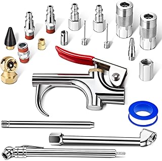
Complete your setup with the right accessories
Inline filters, a quality regulator gauge, and a proper drain valve upgrade all pay for themselves in tank longevity and tool protection.
Shop Compressor Accessories on AmazonMaintenance and Troubleshooting Common Issues
A compressor is one of the more forgiving pieces of shop equipment as long as it receives a handful of basic, regular habits. Neglect tends to show up slowly, in the form of a struggling motor or a rusted-through tank, rather than a single dramatic failure, which is exactly why routine maintenance is so easy to skip and so important not to.
Routine Maintenance Checklist
- Drain the tank after every use to remove condensed moisture.
- Check oil level on oil-lubricated pumps before each use and change oil per the manufacturer’s schedule, typically every few hundred hours of run time.
- Clean or replace the intake filter periodically so the pump isn’t starved for clean air.
- Inspect hoses and fittings for cracking, especially where rubber meets metal fittings.
- Test the safety relief valve a few times a year.
- Check belt tension on belt-driven units, since a loose belt slips and reduces pump output.
Common Problems and Likely Causes
| Symptom | Likely Cause |
|---|---|
| Motor runs constantly, never cuts out | Faulty pressure switch, or CFM demand exceeds pump output |
| Tank won’t build pressure | Worn piston rings, leaking check valve, or major air leak |
| Loud hissing when idle | Leaking fitting, hose, or a stuck-open unloader/check valve |
| Water spraying from the air line | Tank overdue for draining, or missing inline filter |
| Motor hums but won’t start | Tripped thermal overload, low voltage, or seized pump under residual pressure |
| Oil in the compressed air | Worn piston rings or seals on an oil-lubricated pump |
Most of these issues are inexpensive to diagnose and fix if caught early, which is really the entire argument for routine maintenance — a five-minute drain-and-inspect habit is dramatically cheaper than a replacement tank or pump.
When to Repair vs Replace
As a rough rule of thumb, a leaking hose fitting, a worn intake filter, a sticky drain valve, or even a failed pressure switch are all inexpensive, commonly available parts that make repair the obvious choice on an otherwise healthy compressor. A tank that has developed visible rust pitting or a pinhole leak, on the other hand, is not something to patch — a compromised pressure vessel is a genuine safety hazard, and the only responsible option is replacing the unit. Motor and pump rebuilds sit in between: on a higher-end compressor with a cast-iron pump, a rebuild kit can often extend service life for a reasonable cost, while on an inexpensive consumer unit, the labor and parts cost of a full pump rebuild frequently approaches the price of simply buying a new compressor outright.
Finding and Fixing Small Air Leaks
Even a compressor in otherwise good health can develop small leaks at threaded fittings, quick-connect couplers, or hose ends over time, as rubber seals harden and threaded joints loosen slightly with repeated pressure cycling and vibration. The simplest way to find a leak is the same trick plumbers have used for generations: mix a small amount of dish soap with water, brush or spray it onto suspect fittings while the tank is pressurized, and watch for bubbles forming at the leak point. Most fitting leaks are fixed cheaply with fresh thread-sealing tape on NPT threads or by replacing a worn O-ring in a quick-connect coupler, and chasing down these small leaks is worth the effort, since a compressor slowly bleeding air will cycle its motor far more often than necessary, adding wear and electricity cost for no benefit.
Energy Use, Noise, and Efficiency
Two practical concerns come up constantly once a compressor is actually installed in a garage or shop: how much it costs to run, and how loud it is to live with. Both trace directly back to the same mechanical fundamentals covered above.
Electricity Cost and Duty Cycle
A compressor only draws significant power while its motor is actually running, which — thanks to the pressure switch — is a fraction of the total time you’re using air tools, not the entire session. A typical home-shop compressor motor might draw somewhere between 1,500 and 2,000 watts while running, similar to a space heater, but because the motor cycles on and off rather than running continuously, actual energy consumption over a project is usually far lower than that wattage figure alone would suggest. Larger tanks and higher-CFM pumps that can refill quickly and then rest for longer stretches tend to be more electricity-efficient in practice than an undersized unit forced to run nearly continuously to keep up with the same tool.
Why Compressors Are Loud
The hammering, pulsing character of a reciprocating pump is inherently noisier than a smooth rotary design, simply because it’s generating repeated mechanical impacts rather than continuous rotation. Noise ratings are typically given in decibels, and consumer compressors commonly range from the mid-60s for “quiet” oil-lubricated models up into the 80s or even 90s for smaller, high-RPM oil-free units — a meaningful difference in a shared garage or apartment building. If noise is a major concern, oil-lubricated pumps, larger pumps running at lower RPM, and units specifically marketed as “quiet” or “ultra-quiet” — which typically use a different pump geometry and additional sound insulation — are worth seeking out over a compact oil-free unit that happens to be cheaper.
Efficiency Losses Along the Way
It’s worth being realistic that a compressed air system loses energy at multiple points: the motor itself is never 100% efficient at converting electricity to mechanical rotation, the pump loses some energy to friction and heat during compression, and the tool at the end of the line loses more energy converting air pressure back into mechanical motion. None of this is a flaw specific to any one compressor — it’s inherent to how pneumatic systems work — but it’s a reasonable part of why compressed air tools, despite all their durability and simplicity advantages, are generally less energy-efficient at the point of use than direct electric equivalents. For occasional shop use this tradeoff is a non-issue; for a business running air tools all day, every day, it’s worth factoring into the total cost of ownership alongside the purchase price.
Where Compressed Air Shows Up in Everyday Life
Once you start noticing it, compressed air is doing quiet work almost everywhere. In the automotive world, shops rely on compressed air not just for impact wrenches and ratchets, but for tire seating, brake cleaning, and even lifting vehicles on air-assisted hydraulic lifts. In construction and woodworking, framing crews and finish carpenters depend on it for nail guns of every size, from delicate pin nailers used on trim to heavy-duty framing nailers that drive fasteners through engineered lumber in a fraction of a second. Painters and auto-body professionals rely on compressed air to atomize finish coatings through spray guns, where consistent, well-regulated pressure is the difference between a professional finish and an uneven, orange-peel texture.
In manufacturing, compressed air — often called the “fourth utility” alongside electricity, water, and gas — drives pneumatic cylinders, actuators, and robotic end-effectors on assembly lines, valued for its simplicity, reliability, and the fact that a pneumatic actuator can sit stalled under load indefinitely without overheating the way an electric motor would. Dentists’ offices use small, quiet oil-free compressors to drive high-speed drills. Even something as mundane as a gas station’s tire-air machine or the packaged air used to dust electronics is, underneath the branding, running through the exact same intake-compress-store-regulate sequence covered throughout this guide, just scaled and packaged differently for its specific job.
Air Compressor Glossary
| Term | Meaning |
|---|---|
| ASME | American Society of Mechanical Engineers; a rating stamped on tanks built to recognized pressure-vessel safety standards. |
| CFM | Cubic Feet per Minute; the volume of air a compressor delivers over time. |
| Cut-in / cut-out | The low and high tank pressure points at which the pressure switch starts and stops the motor. |
| Duty cycle | The percentage of time a compressor’s motor is designed to run versus rest within a set period. |
| Intercooler | A cooling stage between the two cylinders of a two-stage compressor. |
| PSI | Pounds per Square Inch; a measure of air pressure, or force per unit area. |
| Regulator | The valve that sets output pressure delivered to a tool, independent of tank pressure. |
| Relief valve | A safety device that vents air automatically if tank pressure exceeds a safe limit. |
| SCFM | Standard Cubic Feet per Minute; CFM measured under standardized temperature and pressure conditions for fair comparison between compressors. |
| Unloader valve | A valve that releases residual pressure from the pump head once the motor stops, easing the next startup. |
Bringing It All Together
An air compressor is, underneath the noise and the steel, a wonderfully logical machine: a motor spins a pump, the pump squeezes ordinary air into a smaller volume, that pressurized air waits in a tank until you need it, and a pressure switch and regulator work together to keep the whole system inside safe, useful limits automatically. Once you understand each stage — motor, pump, tank, switch, regulator — every spec sheet, every troubleshooting guide, and every maintenance recommendation starts to make a lot more sense, because you can see exactly which part of the system each one is talking about.
Whether you’re picking your first pancake compressor for occasional trim work or sizing a two-stage unit for a full home shop, the fundamentals in this guide are the same ones that scale all the way up to industrial rotary screw systems. Start with your tools’ PSI and CFM requirements, match tank size to your actual duty cycle, and build good draining and maintenance habits from day one.
It’s also worth remembering that a compressor is a long-term shop investment more than a disposable tool. A well-chosen unit, sized generously enough that it isn’t constantly straining to keep up with your tools, and maintained with the basic habits covered in this guide — regular draining, periodic oil checks on lubricated pumps, clean intake filters, and the occasional leak check — will comfortably outlast several generations of the pneumatic tools you plug into it. Buying based on today’s projects alone is a common early mistake; if there’s any reasonable chance your tool collection or workload will grow, sizing tank capacity and CFM output with some headroom now is almost always cheaper in the long run than upgrading the whole compressor again in a year or two. Treat the pump, tank, and pressure switch covered throughout this guide not as abstract spec-sheet numbers, but as the working parts of a machine you’ll likely rely on for a decade or more of projects.
Read Our Full Buying Guide →Frequently Asked Questions
How does an air compressor actually work in simple terms?
A motor drives a pump that draws in ordinary air and squeezes it into a smaller volume, pushing the pressurized air into a storage tank. When you trigger a tool, that stored pressure flows out through a hose to do work, while a pressure switch cycles the motor on and off to keep tank pressure within a set range.
What is the difference between PSI and CFM?
PSI measures how much force the compressed air can exert, while CFM measures how much volume of air the compressor can deliver over time. Tools need adequate levels of both to run properly without pressure sagging mid-task.
Why does my air compressor’s motor keep starting and stopping?
That cycling is normal and controlled by the pressure switch. It starts the motor once tank pressure drops to the cut-in point and stops it once pressure climbs back to the cut-out point, keeping the tank within a target range automatically.
What is the difference between a single-stage and a two-stage compressor?
A single-stage compressor reaches final pressure in one compression stroke and suits most home and shop needs. A two-stage compressor compresses air twice with cooling in between, reaching higher pressures more efficiently for heavier industrial or continuous-duty work.
Why is there water in my air compressor tank?
Compressing air concentrates the moisture naturally present in it, and that moisture condenses into liquid as the air cools inside the tank. Draining the tank after every use prevents that water from causing internal rust.
What does the pressure regulator on a compressor actually do?
The regulator sets the output pressure delivered to your tool, independent of tank pressure, protecting tools rated for lower pressures than what the tank can hold.
Can an air compressor explode?
It’s rare but possible, generally caused by undrained tank corrosion, a failed pressure switch, or a compromised relief valve. Regular draining, inspection, and never bypassing the safety relief valve significantly reduce that risk.
What is the safety relief valve for?
It’s a mechanical backup that automatically vents air if tank pressure rises above a safe threshold, typically because the pressure switch failed to cut off the motor in time.
How much CFM do I need for common air tools?
Light tools like brad nailers often need under 1 CFM, framing nailers typically need 2 to 3.5 CFM, impact wrenches and sanders commonly need 4 to 8 CFM, and continuous-draw tools like grinders can need 8 to 15 CFM or more.
Do oil-free and oil-lubricated compressors work differently?
Both use the same basic piston-and-cylinder compression principle. Oil-lubricated pumps use an oil bath to cut friction and heat, generally lasting longer and running quieter, while oil-free pumps use permanently lubricated coatings, trading some durability for lower maintenance.
What is the difference between a piston compressor and a rotary screw compressor?
A piston compressor uses a reciprocating piston to compress air in pulses, suiting intermittent use. A rotary screw compressor uses two interlocking rotors to compress air continuously, producing steadier output better suited to industrial, continuous-duty settings.
How long should an air compressor tank last before rusting through?
With regular draining and dry storage, a quality steel tank can last well over a decade, and many manufacturers back tanks with five to ten year warranties. Tanks that are rarely drained can develop damaging internal rust within just a few years.